III. THE ASSASSIN
A. The Alleged Assassination Weapon*
1. INTRODUCTION
- The Warren Commission concluded that CE 139, a Mannlicher-Carcano rifle,
was used to assassinate President Kennedy. (65) This rifle was linked by the
Commission to Lee Harvey Oswald by both fingerprint and cloth fiber analysis,
and by two photographs taken in Oswald's backyard that depict him holding the
weapon. (66) These findings, however, have been questioned on the basis of
observations relative to postassassination photographs of the alleged murder
weapon.
- It has been observed that when various postassassination photographs of
the rifle are enlarged, so that the images of the rifle are the same length,
the respective images do not coincide. One picture may show the rifle as
having a longer barrel and shorter stock than another photograph, and
frequently the component parts do not aline. (67) The Photographic Evidence
Panel was asked to address this issue and to attempt to determine whether CE
139 could be photographically linked to Lee Harvey Oswald.
2. ISSUES
- a. Are the dimensions of CE 139, the alleged murder weapon that is in the
National Archives, consistent with the dimensions of the rifle that Oswald is
shown holding in the backyard pictures and with the alleged murder weapon,
purportedly seized by the Dallas Police Department after the assassination,
that is shown in numerous postassassination photographs?
- b. Can CE 139 be established to be both the same weapon that Oswald is
shown holding in the backyard pictures and that was the subject of numerous
postassassination photographs?
3. MATERIALS AND PROCEDURES
- The Photographic Evidence Panel reviewed the analysis that asserted that
the relative dimensions of the rifle(s) depicted in these photographs were
inconsistent, and perceived immediately that this analysis failed to consider
the effect of perspective on the manner in which an image is depicted in a
photograph. The camera lens projects an image of the three-dimensional world
onto a two-dimensional film plane. This projection usually causes parallel
lines in space to be imaged as converging lines, and causes equally spaced
intervals on a line that recedes from the camera to be imaged progressively
shorter along the receding line.
* This section was prepared under the direction of C. S. McCamy and Cecil W.
Kirk; technical appendices by McCamy and Kirk are included. For related public
hearing testimony, Sept. 14-15, 1978, see HSCA-JFK Hearings, vol. II, pp.349, 397.
- When a long object, such as a rifle, is tilted toward the camera axis
so that one end is farther away than the other, the nearer parts are imaged
larger relative to the central parts and the more distant parts are imaged
smaller. The degree of difference depends on the angle of tilt. This effect
is illustrated in figure III-1. (JFK exhibit F-389). Where the rifle is
represented by a straight line and the camera is represented by the two
essential parts, the lens and the film. Point A is at one end of the rifle,
point B is at the center, and point C is at the other end. The size of the
image can be found by assuming that light passes straight through the center
of the lens. (68) Light from A goes to A', from B to B', and from C to C'.
Figure III-l demonstrates that although the length from A to B equals the
length from B to C, the length from A' to B' is less than half the distance
from B' to C'. The photographic effect of tilt attributable to perspective is
further demonstrated by figure III-2 (JFK exhibit F-207.) where five photographs of one particular rifle depict its relative dimensions differently,
depending on the manner in which the weapon was tilted.
FIGURE
III-1 -- Photographic effect of rifle tilt.
FIGURE
III-2.--Effect of rifle tilt on apparent length.
- Realizing that the failure to consider the effect of tilt was probably
responsible for the observed discrepancies, the Photographic Evidence Panel
conducted a study that took the tilt factor into account. In this study the
tilt angle, distance from rifle to lens and distance from lens to film* were
found that would bring the images of the two ends of the rifle and the rear
flat of the rear sight into conformance with the proportions of the Archives
rifle. Then, using the same constants, the locations of 10 other points on
the rifle were computed from distances measured on the photographs. The two
end points of the rifle and the rear sight served as anchor points for the
calculation, and consequently were not regarded as measured values. Ten other
points were measured for each of 12 photographs on which the points were
visible. The mean value was computed for each point. The average deviation of
the values from the mean of each point was computed, and the deviation of
the mean value from the value for the Archives rifle was computed.
- When the tilt was thus taken into account, the proportions of all the
rifles photographed matched the proportions of CE 139 remarkably close. The
precise procedures followed and calculations employed are set forth in the
appendix to this report in a manner that can be duplicated by any competent
mathematician. The photographs that served as the basis for this analysis are
listed in table 1 of the appendix.
*These factors provided the mathematical basis for photogrammetric computations
that brought these photographic images of the rifle into proportional
conformance with the Archives rifle.
- In addition, 21 photographs were taken of the rifle in the National
Archives in Washington, D.C. on April 18, 1978. The point of view and type of
illumination were varied to simulate some of the conditions under which the
rifle had been photographed at the time of the assassination. See figures III
4a-u in appendix. These photographs were then compared with the preceding
pictures taken in 1963 for the purpose of determining whether any similar
identifying marks could be found on the rifle depicted in both sets of
photographs.
- It was, of course, understood that not all marks would show on all of the
pictures because a given picture shows only one view. Further, different
lighting reveals different scratches and other marks. For this reason, it
could not be concluded that a given mark was not on the rifle at the time of
an earlier photograph just because it was not visible on the photograph. The
22 identifying marks that were detected and the photographs taken in 1963, in
which they are shown are set forth in table 7 of the appendix. Only one of
these, the largest and most prominent, a gouge mark on the rifle's forestock,
was visible on any of the backyard pictures. Nevertheless, this mark was
considered sufficiently distinctive to be a reliable identifying feature. See
appendum D for a discussion of random patterning.
The panel's complete analysis regarding this issue is set forth in the
appendix.
4. CONCLUSIONS
- a. A comparison of the relative lengths of parts of the alleged
assassination rifle that is in the National Archives with corresponding parts
of what purports to be that rifle as shown in various photographs taken in
1963 indicates that the dimensions of the rifle(s) depicted are entirely
consistent. b. A comparison of identifying marks that exist on the rifle as shown in
photographs today with marks shown on the rifle in photographs taken in 1963
indicates both that the rifle in the Archives is the same weapon that Oswald
is shown holding in the backyard picture and the same weapon, found by Dallas
police, that appears in various postassassination photographs.
ADDENDUM
REPORT ON AN EXAMINATION OF PHOTOGRAPHS OF THE RIFLE ASSOCIATED WITH THE
ASSASSINATION OF PRESIDENT JOHN F. KENNEDY *
Introduction
- The alleged assassination weapon was the subject of many photographs. An
hour or so after President Kennedy was shot and killed on November 22, 1963,
the Dallas police found a rifle in the Texas School Book Depository. (69) The
police photographed the rifle where it was found. During the search of the
building, a 16-millimeter motion picture was taken by Thomas Alyea of
television station WFAA. This motion picture film depicts the rifle at the
time that it was discovered by the police. (70) A police officer carried the
rifle from the building and, as he walked east on Elm Street and across
Houston Street, reporter Allen, of the Dallas Times Herald, took a series of
about seven pictures in rapid succession. (71) As the rifle was carried
through the halls of the police station, it was held overhead for reporters to
see. Numerous photographs were taken at that time. During the investigation,
both the Dallas police and the FBI photographed the rifle a number of times in
their photography labs. (72)
- Among Oswald's personal effects, the police found photographs depicting
Oswald standing in his backyard, holding a rifle that looked like the rifle
found in the book depository. These photographs were among the evidence
considered by the Warren Commission. (73)
- Since that time, a number of authors have reexamined the evidence and
raised questions about the conclusions drawn by the Warren Commission. It has
been observed that when some of these photographs are enlarged so that the
various images of the rifle are the same length, the images do not coincide.
The proportions of the lengths of images of component parts of the rifle do
not match. See fig. III 5 (JFK F-208) [White exhibit]. One picture may show
the rifle as having a longer barrel and shorter stock than another picture, or
different components of the rifle simply do not align. (74)
*This section was prepared under the direction of C. S. McCamy.
FIGURE
III-5. -- White Testimony Exhibit.
- Early in 1978, at the request of the committee, photographic panel member
C. S. McCamy, undertook a study of this evidence. He studied two aspects of the
evidence: (1) A comparison of the relative lengths of parts of the rifle,
shown in various photographs taken in 1963, to the corresponding dimensions of
the rifle now in the National Archives in Washington, D.C.; and (2) a
comparison of identifying marks shown on the photographs taken in 1963 with
those shown on photographs he made of the rifle now in the National Archives.
Both lines of investigation revealed facts that support the conclusion that
the same rifle is depicted in all of the pictures examined. The study of
proportions offers strong evidence that the rifle (or rifles) photographed is
(or are) of the same kind. The comparison of identifying marks offers strong
evidence that only one rifle is involved. The claims of gross mismatch are
clearly refuted.
Relative Length Comparisons
- The artist knows that parallel lines in three-dimensional space must be
depicted as converging lines on a two-dimensional representation, and that
equally spaced intervals on a line must be depicted as progressively closer as
the line recedes from the viewer. This kind of rendering is automatically
performed by the camera lens. Nevertheless, the human visual system, involving
both the eye and brain, interprets photographs as though they were objects in
three-dimensional space. We rarely notice the rendering of perspective in
pictures, as long as the pictures look natural.
- The various pictures of the rifle were taken at various angles. Viewed
naturally, normal perspective causes parts of an object tilted towards the
camera to appear lengthened relative to those parts that recede from the
camera. See figure III-1 (JFK F-389) (rifle tilt). The extent to which this
phenomenon occurs is a function of the degree to which the object, here a
rifle, is tilted relative to the camera. Accordingly, in order to make a valid
study of an object's relative length as depicted in photographs, the tilt
factor attributable to perspective must be taken into consideration. This can
be done using the same type of analysis that is employed in the making of
maps.
- Most maps are now made by transferring measurements from aerial
photographs. If the camera carried by the airplane is tilted with respect to
the vertical direction, the effect of perspective must be taken into account.
Thus, the matter dealt with here is an everyday problem, well understood by
those who practice photogrammetry, the science of using photography to measure
dimensions. (75)
- It would have been possible to have these measurement studies done by
highly automated methods in a mapping agency of the U.S. Government, but to
achieve the highest degree of acceptance and popular understanding of the
methods, special simplified forms of photogrammetric equations were derived
and are set forth in addendum A. All measurements on photographs were made
with an ordinary millimeter scale and hand magnifier, and all calculations
were performed with a commonly available pocket calculator having a memory and
trigonometric functions. These mathematical derivations can be followed by a
typical high school mathematics teacher, and all of the operations can be
repeated by anyone with adequate patience and the intelligence to do
calculations. The procedures are admittedly very laborious.
- The photographs that were the subject of this analysis are listed in table
No. 1. With the exception of the picture taken by the Federal Bureau of
Investigation, these pictures are enlarged prints of small negatives. The
enlargement ratio or magnification of the enlarger M is the ratio of the
length x' of an image on the enlarged picture to the length x of the
corresponding image on the negative: M=x'/x. From this it follows that a
distance on the negative x can be computed from the corresponding distance x'
measured on the enlarged print and the magnification M by the following
formula:
x=x'/M
The magnification of a contact print is 1.
- Since the objective is to compare lengths along the bore of the rifle or
lines parallel to it, it is possible to work with the simple equation for
computing distances along a straight line, rather than the more general
three-dimensional photogrammetric equations. In practically all cases, the
line of the rifle image passes nearly through the center of the picture and
almost always the rear sight is near the center. Thus figure 6 is fairly
representative. The derived equations also are valid if the rifle image is
displaced from this central position. In that case, the image distance derived
would not be the axial image distance,* (3) but the distance from the image of
the rear sight to the rear nodal point * (2) of the lens. The computed
proportions of the rifle would not be affected.
FIGURE
III-6. -- Geometric relationship of camera to the rifle titled at an angle
t.
- As shown by the equations set forth in addendum A, when one point of an
object is imaged at the center of a photograph, the actual distance X between
that point and another point on the object may be calculated by measuring the
corresponding distance x between these points on the photograph itself. This
may be accomplished if we know the angle of title t between the linear object
and a plane normal to the optical axis * (1) of the camera lens, the distance
u from the center of the object to the front nodal point* (2) of the lens, the
axial image distance v, and the distance from the rear nodal point of the lens
to the camera image. The equation is:
x= ux/ (vcost - xsint)
If we know u and the focal length* (4) of the lens, we can compute v, using the following equation:
v= uf / (u-f)
*These technical terms may be defined as follows:
(1) The optical axis is the
line joining the center of the lens and the center of the image area.
- In the present case, neither the distance u from the rifle to the camera
lens, nor the angle of tilt t, nor the axial image distance v, is usually known. Most
of the information needed to compute a distance, X on the photographed rifle
from a distance x on the negative is lacking. Nevertheless, the objective is
not to compute such lengths; rather, it is to compare relative proportions of
the parts of rifles photographed with the proportions of parts of the rifle in
the Archives. To accomplish this, it is only necessary to scale the length of
each rifle photographed to the length of the rifle in the Archives. The tilt
angle t that makes the ratio of the length from the rear sight to muzzle and the
length from rear sight to butt is the same as the corresponding ratio on the
Archives rifle.* The tilt angle t is found by the following equation, which is
based on the scaling described:
tan t = ( (X2 / x2) - (X1 / x1) )( v / (X2-X1) )
where: t is the tilt angle
X2 is the length on the Archives rifle from rear
sight to one end,
x2 is the length on the negative image from rear sight to one
end,
X1 is the length on the Archives rifle from rear sight to the other end,
x1
is the length on the negative image from rear sight to the other end,
and v is
the axial image distance (lens to film)
The subscript 1 is assigned to the
distance corresponding to the end of the rifle tilted away from the camera,
and 2 is for the end tilted toward the camera. All measurements were from the
vertical plane of the rear sight.
(2) The
front nodal point is the point of view from which the scene is imaged by the
camera. The rear nodal point of the lens is the corresponding point in image
space. The ray of light from the rear nodal point of the lens to an image
point is parallel to the ray from the corresponding object point to the front
nodal point of the lens.
(3) The axial image distance is the distance along
the optical axis from the rear nodal point of the lens to the center of the
image area.
(4) The focal length is the axial image distance when the camera
is focused on an infinitely distant object.
*It may be mistakenly argued
that this analysis seems to take for granted that to be proven because the
angle that is found makes the 2 ends and the middle of the rifle image
correspond to the proportions of the rifle in the Archives. Nevertheless, once
the angle of tilt and the distances are found, 10 other distances are computed
using the same equation. The degree to which these 10 distances correspond to
distances on the Archives rifle is the basis for determining whether the rifle
photographed has the same proportions as the Archives rifle.
- As one looks at a photograph, depending on the degree of tilt, it may or
may not be obvious whether the muzzle was tilted away from the camera or
toward it. There is a mathematical test that can be applied to the
measurements on the photograph to determine which way the muzzle was titled,
assuming that the photographed rifle does, in fact, have the same proportions
as the Archives rifle. The sight-to-muzzle length divided by the sight-to-butt
length of the rifle in the Archives is 465.8/553.0. If the corresponding ratio
for lengths measured on the photograph is less than this number, the muzzle
was foreshortened because it was tilted away from the camera. If the ratio is
greater, the muzzle was tilted toward the camera.
- For the sake of convention, each measurement of sight-to-muzzle and
sight-to-butt length was assigned a positive or negative number, depending
upon which way these respective parts were tilted in relation to the camera.
The respective part tilted away from the camera was assigned the positive
number and the respective part tilted toward the camera was assigned the
negative number. See table 3.
- If the tilt angle t, the axial image distance v, the length X1, on the
Archives rifle, and x1 on the photographic negative are known, it is possible
to compute the distance u from the center of the object (the rear sight of the
rifle photographed) to the camera lens:
u= (X1 / x1)(v cos t = x1 sin t)
- Given these five relationships, the following sequence of operations were
used to compare a photographed rifle with the rifle in the Archives. The
lengths of many parts of the rifle in the Archives were measured. The points
to which measurements were made are named in table 2 and the measured
distances are given in the first column of table 5. All lengths were measured
along lines parallel to the bore. The corresponding lengths were measured on a
photograph. Twelve photographs, representative of all the photographs examined
(see table 1) were selected for measurement. These measurements are given in
table 3.
- When the negatives were available, as was the case for photographs by
William Allen, Dallas Police (one instance), and McCamy, the enlarged
magnification was computed from material deleted, see text measurement of the
distance between frame borders depicted on the enlargement and measurement of
the actual distance between frame borders by the Geological Survey. In all
other cases, magnification was estimated.*
- The focal lengths of camera lenses were known for the backyard photograph
(calibrated by the Geological Survey; see Addendum B), McCamy's photograph
(calibrated by McCamy), and the Dallas Police laboratory photographs (nominal
focal length supplied by Dallas Police).(76) Other focal lengths were
estimated by taking into account common practice at the time the photographs
were made. The object distance u was measured for the McCamy photograph. In
all other cases, it was estimated.
*Magnification, focal length, and object distance were estimated by knowing or
assuming the size camera used and by visual inspection of the given print.
These first estimates provided a starting point for the computations. A series
of computations refined the estimates until a consistent set of values was
found. If the assumed camera size were erroneous, the assumed magnification
would be wrong and the axial image distance computed would be off by the same
factor. These effects would cancel, so the erroneous estimates would not
affect the determination of the proportions of the rifle. It would be
immaterial whether we were measuring a 2x enlargement of a negative 4 inches
wide or an 8x enlargement of a negative 1 inch wide.
Sequence of Computations
-
- Based on known or estimated object distance and focal length, the first
estimate of axial image distance v was computed by the second equation in
paragraph 207.
- Based on known or estimated magnification, negative image lengths x
were computed from measured corresponding lengths x' on enlargements by the
last equation in paragraph 205.
- A first estimate of tilt angle t was computed by the equation in paragraph
208.
- A second estimate of object distance u was computed by the equation in
paragraph 211, based on the first estimates of v and t.
- A second estimate of axial image distance v was computed by the second
equation in paragraph 207, based on the second estimate of u.
- A second estimate of t was computed based on the second estimate of v.
- A third estimate of u was computed based on the second estimates of v
and t.
- The computations were done repeatedly, each time using the last computed
estimates of t, u, and v. From one computation to the next, the successive
approximations changed less each time until, finally, no appreciable change
was found from one computation to the next. This determined the set of
values of u, v, and t that scaled the two main parts of the photographed
rifle to the Archives rifle and took into account the tilt angle.
- Given u, v, and t, the first equation in paragraph 207 was used to compute
the lengths X of various parts of the rifle as deduced from the lengths x of
corresponding parts on the negative image. The computed lengths X of the parts
of the rifle could then be compared directly to measured lengths of parts of
the Archives rifle. If the lengths of various parts of a photographed rifle
were proportional to corresponding parts on the Archives rifle, the lengths
computed by this procedure would match the lengths measured on the Archives
rifle.
- In performing these calculations, the same scale for all measurements was
used. It was uncalibrated except that the centimeter divisions were checked
for consistency. The rifle was measured with an uncalibrated steel metric
tape.
- The results of these calculations are set forth in tables 4 and 5. In each
instance, the relative lengths of the corresponding measured parts were found
to be proportional, and the resulting computed lengths matched very closely.
In performing the computations, it is important to bear in mind the sign of X
and x. They are negative when referring to the part of the rifle tilted toward
the camera. In particular, the second term in the denominator of the first
equation in paragraph 207 is a negative quantity toward one end of the rifle
and positive toward the other.
- The two endpoints of the rifle and the rear sight are anchor points for
the analysis, so they should not be regarded as measured values. Each of 10
other points was measured by the technique given for all of the 12 photographs
on which the points were visible. The mean value was computed for each point.
The average deviation of the values from the mean of each point was computed.
The deviation of the mean value from the value for the Archives rifle was
computed. All of the data are given in table 5.
- The computed distances were within 3 or 4 millimeters of the corresponding
distances on the rifle in the Archives; this reflects an approximate error of
1 percent between the actual lengths on the rifle and the lengths computed
from the photographs. A comparison of tables 3 and 5 shows that the computed
distances involved multiplication factors ranging from 4 to 17 times the
distances measured on the photographs. Thus, the errors of measurement were
magnified by these amounts. Since measurement errors of a small fraction of a
millimeter should be expected, such errors would reasonably account for the
deviations from the Archives rifle.
- The agreement of the data clearly contradicts the claims of gross
discrepancies in proportions of the rifles photographed and offers strong
evidence that the rifle or rifles photographed had the same proportions,
within reasonably expected experimental error. The only way that there could
have been a rifle depicted in these photographs with proportions substantially
different from those of the Archives rifle, and yet matched when
mathematically oriented at the computed angle t and distance u, would have
been if someone deliberately manufactured a special rifle with all dimensions
distorted in precisely the right way to appear to match when viewed at some
angle other than t. In that case, it would have been necessary to align this
specially contrived rifle and the camera very meticulously at the time the
pictures were made. It is highly unlikely that anyone could have perpetrated
such a ruse without detection in front of the Book Depository or in the halls
of the Dallas Police Station a few hours after the assassination of the
President. Aside from this possibility, the method used would show close
agreement only if the photographed rifle had the same proportions as the
Archives rifle, within reasonably expected experimental error, and, of course,
this is not what has been claimed by Warren Commission critics. (77)
- In making the measurements, it is necessary to give some attention to
perspective. The simple equations refer to a line, that is, the centerline of
the bore of the rifle. They also apply to nearby lines parallel to that line.
Nevertheless, if the rifle is tilted and twisted about the centerline, as
shown in figure 7, the twist throws the image of the butt to the right. In
making the measurements, this must be judged and the line drawn from the butt
to the centerline must be angled in keeping with the perspective; this means
that the solid line in figure 7, rather than the dotted line which is
perpendicular to the centerline, must be used. This comes quite naturally if
we let our visual sense guide us. (Notice that even in the crude drawing of
fig. 7, the dotted line does not appear to be perpendicular to the centerline.
This is an optical illusion. If the perspective is sensed, the solid line
appears to be more nearly perpendicular.) High precision requires this
technique to be used for all measurements when the endpoints are not the same
distance and direction from the centerline. The case illustrated in figure 7
is an exaggeration of photograph 11 (see table 1), where the form of the butt
provides a clear indication of the perspective angle.
FIGURE
III-7. -- Taking perspective into account in measuring distances of points
off the centerline of the rifle bore, such as the butt, comb, trigger, and
trigger guard.
- The backyard photograph presented some special problems. The hand obscures
the exact location of the rear sight. (See fig. III-3a.) A nearby groove on the
outside of the chamber was visible and the rear sight was located relative to
this groove. The rear sight was not centered in the photograph but the rear
end of the bolt was. The analysis was done relative to the rear end of the
bolt and the lengths were then translated to be zero at the rear sight for
comparison with the Archives rifle.
- Vertical lines near the edge of the picture bow out very appreciably at
top and bottom. This is known as "distortion." The distortion of the lens said
to have been used to take this picture was measured by the Geological Survey.
The image lies along the diagonals designated 90° and 270° by the Geological
Survey. The reported distortion along this axis was plotted and appropriate
distortion corrections were interpolated on this plot. The distortion
correction was 0.2 mm for points 6 and 7. It was negligible for all other
points. Since the distortion was positive, these amounts were subtracted from
distances computed for the original negative image from measurements on the
enlargement. No distortion corrections were made for other photographs or for
the enlarging lenses because no distortion information about the cameras that
were used to take these photographs was available. Nevertheless, since the
photographs other than the backyard photograph were professionally made, the
lenses probably had very small distortion.
- In addition to the photographs of this rifle, a photograph made by the
Metropolitan Police Department of Washington, D.C., of a different specimen of
the same kind of rifle was examined and analyzed for the purpose of
determining whether the relative properties of Mannlicher-Carcano rifles are
necessarily identical. See figure III-8, No. 4 and No. 5. (JFK exhibit F-206)
The data are shown in the tables for picture No. 21.
- The metal parts coincide very well except for the rear of the bolt. In
this photograph only, the bolt appears to be in the firing position. In all
other photographs, it is in the cocked position. This being the case, such a
discrepancy should be expected. The only point of comparison of the wooden
stocks is the comb, and the computed distance to the comb on this extra
specimen is outside the range of computed values of this distance on all the
photographs of the Archives specimen. This suggests that there were small
differences in manufacturing the wooden parts. This is borne out by the
further observation that two angles on the butts are measurably different on
photographs 20 and 21 by the Metropolitan Police Department. The rear line of
the butt is at an angle to the perpendicular to the bore. On the Archives
specimen it is 6.5°; on the extra specimen it is 10°. The bottom
straight line of the stock is at an angle to the bore. On the Archives
specimen it is 18°; on the extra specimen it is 19°.
- There are many sources of error not accounted for in this analysis. The
distortion of camera and enlarging lenses has been mentioned. In addition,
film changes size and shape during processing and subsequent to processing as
the temperature and humidity change. The same may be said of paper prints.
Finally, there are natural limits to the precision of measurements involving
decisions as to the exact endpoints to set on, interpolation, parallax,
inaccuracy of the scale used, and alinement of the scale with the center line.
Ultimately, however, when the computed distances were scaled to the
photographs, the deviations from the Archives rifle amounted in most cases to
a small fraction of a millimeter. It would be reasonable to expect that the
effect of the potential errors cited would be of that magnitude.
Identifying Marks
- Twenty-one photographs were taken of the rifle in the National Archives in
Washington, D.C., on April 18, 1978. These photographs, figures 4a-u, are
numbered from A-1 to A-21 in the upper right-hand corner. See table 6.
Identifying marks are lettered on the photographs. Table 7 indicates the
earlier photographs from the preceding section on which the same marks may be
observed. There are 56 citations of 22 different identifying marks on the
early photographs, and 13 on photograph of the alleged assassination weapon
that was recently made by the Metropolitan Police Department of Washington,
D.C. The list of identifying marks includes the more prominent markings found
on the photographs from the preceding section but is not exhaustive. In many
cases, smaller or less prominent nearby marks are seen as well.
- Identifying mark L refers to the pattern of vertical lines apparently left in
the horizontal groove by the woodworking operation used in manufacturing the
stock. These may be regarded as several points of evidence. The mark "VE
[trefoil] K" (identification mark U), the date "November 22, 1963," and "PMS" or "RMS"
"November 1963", have been scratched into the butt, as shown on pictures A-6, A-10,
A-11, A-16, and A-21, possibly by law enforcement officials. Only the trefoil
of mark U appears on the Fort Worth Star Telegram photograph No. 13 in table
1, but the initials in identification mark U are seen on photograph No. 15
taken by the Dallas Police Department later that day. The lighting revealing
the trefoil should have revealed the initials immediately to either side of it
in picture 13 if they were, in fact, there at the time that the picture
was taken. None of the cited identifying marks were observed on photograph No.
21 of another specimen of the same kind of rifle.
FIGURE
III-4a.--MeCamy's Archives rifle photograph.
FIGURE
III-4b.--McCamy's Archives rifle photograph.
FIGURE
III-4c. --McCamy's Archives rifle photograph.
FIGURE
III-4d. --McCamy's Archives rifle photograph.
FIGURE
III-4e. --McCamy's Archives rifle photograph.
FIGURE
III-4f. --McCamy's Archives rifle photograph.
FIGURE
III-4g. --McCamy's Archives rifle photograph.
FIGURE
III-4h. --McCamy's Archives rifle photograph.
FIGURE
III-4i. --McCamy's Archives rifle photograph.
FIGURE
III-4j. --McCamy's Archives rifle photograph.
FIGURE
III-4k. --McCamy's Archives rifle photograph.
FIGURE
III-4l. --McCamy's Archives rifle photograph.
FIGURE
III-4m. --McCamy's Archives rifle photograph.
FIGURE
III-4n. --McCamy's Archives rifle photograph.
FIGURE
III-4o. --McCamy's Archives rifle photograph.
FIGURE
III-4p. --McCamy's Archives rifle photograph.
FIGURE
III-4q. --McCamy's Archives rifle photograph.
FIGURE
III-4r. --McCamy's Archives rifle photograph.
FIGURE
III-4s. --McCamy's Archives rifle photograph.
FIGURE
III-4t. --McCamy's Archives rifle photograph.
FIGURE
III-4u. --McCamy's Archives rifle photograph.
- Significantly, the largest and most prominent mark, mark S, a gouge mark
that appears on the backyard picture, also appears in the gun as it is
portrayed in the Alyea movie sequence and in three other postassassination
photographs of the rifle as well. See table 7. While the FBI was disinclined
to testify to the Warren Commission that this gouge mark was sufficiently
unique to warrant a positive identification of the assassination weapon as the
same gun that Oswald is shown holding in the backyard picture, (78) the
Panel's forensic photographic specialist considered this mark to be a random
patterning sufficient to warrant a positive identification. See figure III-8
(JFK exhibit F-206 and addendum C).
FIGURE III-8-(JFK exhibit F-206) Identifying mark S (gouge on forestock)
considered to be a "random pattern." (See addendum D.) Clockwise from left:
Enlargement of Archives rifle shows mark S (No. 1); Archives rifle (No. 2) and
another Mannlicher-Carcano (No. 3)-mark S only visible on No. 2;
deMohrenschildt print of CE 133-A (No. 4) and Fort Worth Star Telegram
photograph of rifle shortly after discovery (No. 5); marks visible on
enlargements of both photographs.
- Finally, the most common misconception regarding photographic evidence is
the idea that all photographs of the same object must look alike. The
appearance of the image depends on level and directions of illumination, point
of view, kind of film or plate, exposure, focus, and a host of other factors.
Pictures A-l, A-2, and A-3 in this series were made with the camera and rifle in
the same position; only the lighting was changed. Note the difference in
appearance, particularly in the wooden parts. Picture A-1 is directionally
lighted from the upper left, picture A-3 from the upper right, and picture A-2
was diffusely lighted from overhead. The same kinds of differences are seen in
A-5 and A 6, in A-7 and A-9, in A-6, A 7, and A-8 and in A-10 and A-21. Note that
mark A appears light on a dark background on picture A-l, but dark on a light
background in picture A-2, simply because the lighting is different. One must
be careful not to conclude that marks were not on the rifle at the time a
picture was made simply because the marks are not seen in the picture.
Conclusion
- 1. A comparison of the relative lengths of parts of the alleged
assassination rifle that is in the National Archives with corresponding parts
of what purports to be that rifle as shown in various photographs taken in
1963 indicates that the dimensions of the rifle(s) depicted are consistent.
- 2. A comparison of identifying marks that exist on the rifle as shown in
photographs today with marks shown on the rifle in photographs taken in 1963
indicates both that the rifle in the Archives is the same weapon that Oswald
is shown holding in the backyard picture, and the same weapon that was seized
by Dallas Police and appears in various postassassination photographs.
TABLE
1.--PHOTOGRAPHS ANALYZED
[In chronological order of original image]
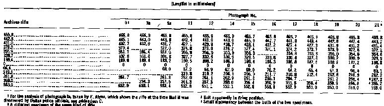
TABLE 2.--Selected points on the rifle and rifle images
(Measurements were
made from the rear sight to each selected point )
- Muzzle.
- Front of band supporting front sight.
- Rear of band supporting front sight.
- Front end of bayonet mount.
- Front end of bayonet mount ring.
- Front end of ring over the stock clamp.
- Front end of stock band.
- Rear flat of rear sight.
- Front of trigger guard.
- Front of trigger.
- Rear of bolt (bolt closed).
- Comb.
- Butt.
TABLE
3--LENGTHS MEASURED ON ENLARGEMENTS (mm)
TABLE 4--DERIVED
PHOTOGRAMMETRIC CONSTANTS
TABLE
5--COMPUTED LENGTHS OF PHOTOGRAPHED RIFLE COMPONENTS COMPARED TO MEASURED
COMPONENTS ON ARCHIVES RIFLE
TABLE
6.--Photographs of rifle in the Archives exhibiting identifying marks
FIGURE
III-3a.--Table 7. Table 1 (photograph No. 0).
FIGURE
III-3b. --Table 7. Table 1 (photograph No. la). (See attachment e).
FIGURE
III-3c. --Table 7. Table 1 (photograph No. 3a).
FIGURE
III-3d. --Table 7. Table 1 (photograph No. 5a).
FIGURE
III-3e. --Table 7. Table 1 (photograph No. 11).
FIGURE
III-3f. --Table 7. Table 1 (photograph No. 12).
FIGURE
III-3g. --Table 7. Table 1 (photograph No. 13).
FIGURE
III-3h. --Table 7. Table 1 (photograph No. 14).
FIGURE
III-3i. --Table 7. Table 1 (photograph No. 15).
FIGURE
III-3j. --Table 7. Table 1 (photograph No. 16).
FIGURE
III-3k. --Table 7. Table 1 (photograph No. 18).
FIGURE
III-3l. -Table 7. Table 1 (photograph No. 20).
TABLE 7.-PHOTOGRAPHS DEPICTING IDENTIFYING MARKS
|
Exhibit No. |
Photographic No. from table 1 |
identifying marks |
|
III-3a |
0 (backyard) |
S. |
|
III-3b |
la Alyea movie |
A,B,C,D,H,S. |
|
III-3c |
3a Dallas Times |
B,E,W. |
|
III-3d |
5a Dallas Times |
B,E,F,G,W. |
|
III-3e |
11 Fort Worth Star Telegram |
A,C,D,G,J,K. |
|
III-3f |
12 United Press |
A,D,K,L,M,N,O,S,T. |
|
III-3g |
13 Fort Worth Star Telegram |
E.P.Q. part of U.W. |
|
III-3h |
14 Dallas Police |
E.P.Q. |
|
III-3i |
15 Dallas Police |
E,F,P,Q,U. |
|
III-3j |
16 Dallas Police |
C,D,H,R,S,T. |
|
III-3k |
18 FBI |
A,C,D,H,R (appears light), S.V. |
|
III-31 |
20 Washington Police |
A,C,D,H,J,K,M,N,O,S,T,V. |
TABLE 8.--ERROR ANALYSIS
ATTACHMENT
A
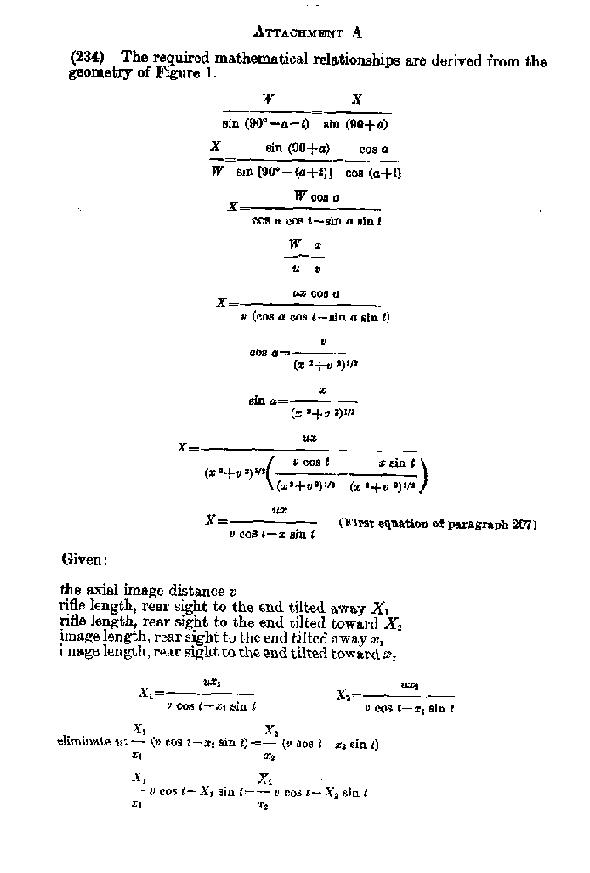
- The required mathematical relationships are derived from the geometry of
Figure 1.
Given:
the axial image distance v
rifle length, rear sight to the end tilted away X1
rifle length, rear sight to the end tilted toward X2
image length, rear sight to the end tilted away x1
image length, rear sight to the end tilted toward x2
The equation in paragraph 205 and the second equation in paragraph
207 are well known in elementary optics.
ATTACHMENT
B
No. 009215.
- U.S. DEPARTMENT OF THE INTERIOR,
GEOLOGICAL SURVEY,
Reston, Va., May 5, 1978.
REPORT OF CALIBRATION
OF 2 1/4 X 2 1/4 CAMERA
Camera type 620 Imperial Reflex.
Lens type DUO.
Nominal focal length 77
mm.
Camera: Commission.
Identification: Exhibit No. 750.
Maximum aperture
f/12.5*.
Test aperture f/12.5.
SUBMITTED BY SELECT COMMITTEE ON ASSASSINATIONS, U.S. HOUSE OF
REPRESENTATIVES
Reference: Letter dated March 2, 1978 from Mr. Michael Goldsmith.
These
measurements were made on Kodak Verichrome Pan film type 620, developed in
D-19 at 68° F for 3 minutes with continuous agitation. This film was
exposed on a multicollimator camera calibrator using a white light source
rated at approximately 3500K.
I. Equivalent Focal Length: 77.55 mm.
This measurement is considered
accurate within 0.02 min.
II.--RADIAL DISTORTION
*This is a nominal value as the shutter is not equipped with either a T
(Time) or B (Bulb) setting for holding the aperture in the open position.
The radial distortion is measured for each of 4 radii of the focal plane
separated by 90° in azimuth. D is the average distortion for a given
field angle. Values of distortion D are based on the equivalent focal length
referred to the field angle co-tangent for 7.5°. The radial distortion is
given in micrometers and indicates the radial displacement of the image from
its distortion free position. A positive value indicates a displacement away
from the center of the field. These measurements are considered accurate within 10
µm. It is clear from these variations in the values reported among the four
radii from the average that a substantial amount of asymmetric distortion is present in
this lens.
III- RESOLVING POWER IN CYCLES/MM The resolving power is obtained by
photographing a series of test bars and examining the resulting image with
appropriate magnification to find the spatial frequency of the finest pattern in which the bars can be counted with reasonable confidence. The series of patterns has spatial frequencies from 10 to 223 cycles/mm in a geometric series having a ratio of the 4th root of 2. Radial lines are parallel to a radius from the center of the field, and tangential lines are perpendicular to a radius.
IV. Indicated Principal Point
Positions of all points are referenced to the indicated principal point as origin. The diagram indicates the orientation of the referenced points when the camera is viewed from the back. The direction of film travel is to the top.
Indicated principal point of midsides of focal frame:
A----------Unable to measure.
B----------28.79 mm.
C----------27.96 mm.
D----------29.34 mm.
These measurements were made from a shadow image formed in the focal plane.
The method of measuring these distances is considered accurate within 0.01 mm.
The camera was aligned for calibration by autocollimating on the mounting
surface where the front of the test camera-lens was placed for the film
exposures. It is evident, however, that this is an indirect procedure, but the
only method possible for a camera of this type. This alinement process made
the front of the lens ring normal to the axis of the collimator beam emergent
from the 0° collimator.
V. Camera Negative
The diagram indicates the orientation, with emulsion-up of a negative
submitted for focal frame measurements.
Distances between midsides:
A-B--------------------57.10 mm.
C-D--------------------57.14 mm.
The method of measuring these distances is considered accurate within 0.01
mm.
WILLIAM P. TAYMAN
Branch of Research and Design,
Topographic Division.
ATTACHMENT C
ALYEA FILM STUDY
(By C. S. McCamy)
- After the President was shot, the Dallas police searched the Texas School
Book Depository and found a rifle. While the search was in progress, a motion
picture was being made by T. Alyea of Dallas television station WFAA. I
studied a 16-mm copy of that motion picture film. I did not find a
satisfactory single frame displaying entire length of the rifle. The frame
selected for analysis was about 55 feet into the film. It depicts a man
displaying the rifle in the book depository. The frame may be identified by a
prominent link mark on the film that is located on the image of the man's
shoulder. Measurements to the nearest 0.0001 inch were made on the film by
means of a Nikon measuring microscope. The computed constants were: tilt
angle t = 23.1° with the muzzle tilted away from the camera, object
distance u = 2511 mm, and image distance v = 25.66 mm. The measured and
computed distances were as follows:
The conformity is well within the errors that might reasonably be expected
when measuring such a small film. The very large deviation with respect to the
front of the trigger guard should not be regarded as very significant because
that piece of the rifle curves around to meet the line of the forestock in
such a way that it is difficult to see or set a hairline on where it ends. The
bolt, comb, and butt were not visible in this frame.
ATTACHMENT D RANDOM PATTERN ON OSWALD RIFLE
(Sgt. Cecil Kirk)
- As a piece of equipment is utilized, either properly or abused, one can
expect that the utilization or abuse will leave individual artifacts or damage
on that equipment that, when evaluated together, will be found to be unique to
that piece of equipment. For example, an automobile that is 2 or 3 years old
provides a classic example of random patterning. The nicks and dents on the
doors and sides of the vehicle are mostly caused by the doors of other cars
being pushed against it in parking lots. Because the car is parked in several
locations adjacent to many cars of differing sizes, a pattern of abuse will
develop on the vehicle. As that vehicle is driven, it will occasionally be
struck by stones and other roadway debris that add additional nicks and dents
to the surface of the vehicle. Minor damage caused by insignificant accidents
will add other identifiers to the random pattern which in turn will make it
even more unique. These are the elements that make up the pattern of artifacts
caused by utilization of the vehicle.
- A military rifle will also establish a random pattern on its surface.
After the weapon is disposed of by the military and is sold, stored, and
resold as a civilian sporting weapon it will receive other elements of its
individual pattern of damage. The Mannlicher-Carcano rifle in this case
displays its own pattern of identifiers--its pattern of damage. Of the
numerous artifacts on this particular weapon--one mark or pattern of abuse is
very distinctive. It is a rather large gouge in the forestock of the weapon.
It has a measurable shape, and, because of its depth, photographs of the rifle
reflect the gouge in a manner not unlike a crater on the moon, a tire
impression on a muddy road, or a tool mark in soft metal.
- In the Lee Harvey Oswald backyard photographs identified as 133A Stovall,
133A de Mohrenschildt, and CE-134, that same gouge is quite visible and can be
measured and compared with the gouge on the questioned rifle. They are
identical in every respect.
- Based upon this system of identification, the rifle in these photographs
can be positively identified as the same rifle that is presently in the
custody of the National Archives. Finally, it should be noted that although an
FBI expert declined to make a positive identification of the rifle in question
based upon this gouge mark, this expert did not have access to all of the same
quality photographic prints that were available to the Panel. For example, the
133A de Mohrenschildt and 133A Stovall prints, both of which are of high
quality, were obtained and reviewed by the committee in 1977 and 1978
respectively. This was the first time that these materials were analyzed. In
addition, positive identification of the rifle was based upon an examination
of CE-134, a very good enlargement (from the original negative) of CE-133A.*
The FBI's expert in 1964, however, apparently did not consider this photograph
in reaching his conclusion.
B. Alleged Alibi Evidence-The Billy Lovelady Issue
[See pars. 759-70
infra.]
*Ibid.